My rear wheel is on and centered (which is covered in Sportster Chopper Part 4) and now it is time to figure out what to do for a rear brake. The stock single piston caliper rear brake is perfectly fine for stopping a lightweight Sportster, but the bracket needs some modifications to make it fit into a motorcycle hardtail frame.
For this article I’ve decided to take a deep dive into using modern technology to help make a better chopper. I know everyone prefers old school techniques, but sometimes you must admit that there are better and easier ways to do things even if they don’t seem as cool. So, to start off, I’ll be showing how to use a digital camera and a couple software programs to create a precise template for modifying a stock rear brake bracket.
Redesign Bracket for Sportster Brakes Upgrade
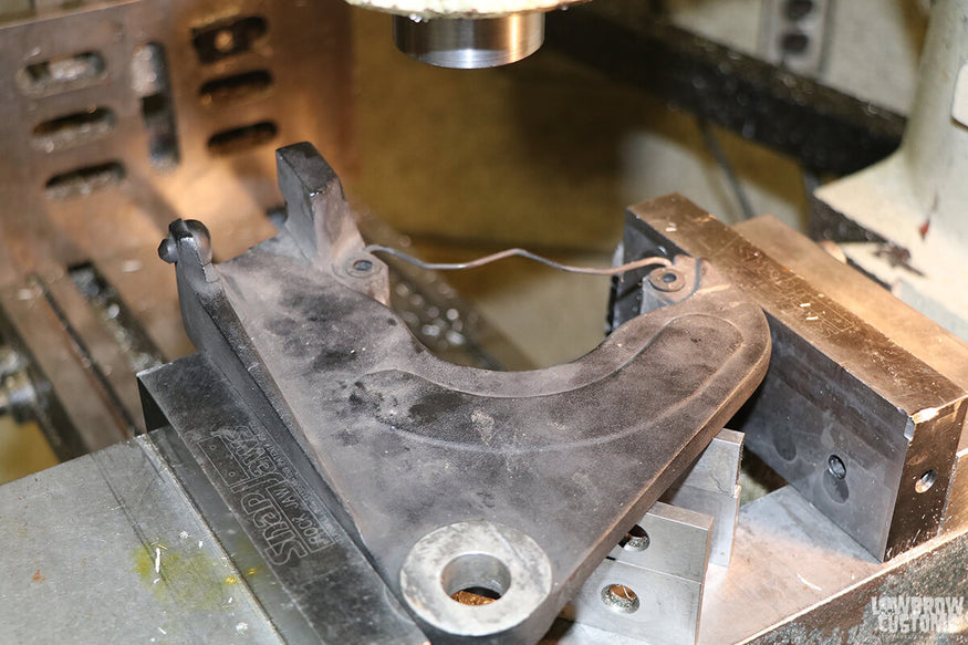
Preparing to mill off some unneeded parts from a rear brake bracket.
Trim Down Two Raised Sections
From the factory, the rear brake bracket is designed to use the swingarm to keep it from rotating via two raised sections of the casting that straddle the swingarm. Switching to a hardtail frame eliminates the need for these portions of the bracket, so the first thing I did to rebuild the Sportster brake bracket was remove them with a milling machine.
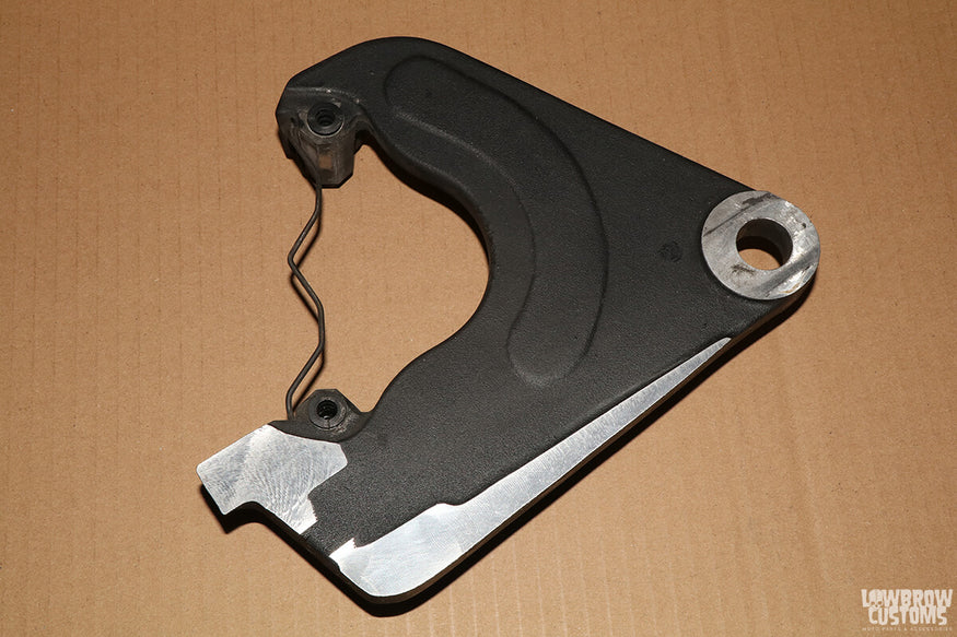
Rear brake bracket after excess material has been trimmed.
Get the Sportster Brake Bracket into a Digital Format
Now you can see from the above photo that the resulting bracket is wider on one side than the other. I could just leave it this way, but I need to make up for all that extra weight I added with those stainless steel axle spacers...
I basically just wanted to mirror the left side and decided instead of just tracing out a pattern on a piece of cardboard, I would up the ante and go digital. The first step was to capture a photo of the part from directly above. For this step I used a tripod and a little additional lighting to remove most of the shadows from around the part.
I also used an app to turn my phone into a bubble level, so I could get both the camera and the bracket perfectly squared to one another. An easy way to check that the camera and bracket are square is to make sure that you can not see the sides of the axle hole.
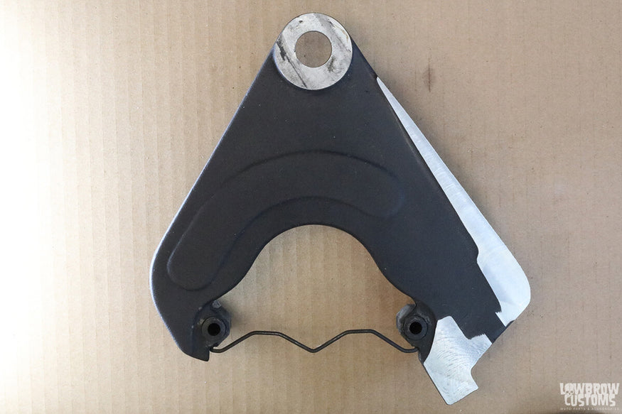
It’s important to light the part so that there are minimal shadows.
Create a Custom Brake Bracket Using Graphic Design Software
It took a few tries but once I got a photo I was satisfied with, I opened using Photoshop. If you don’t have Photoshop, don’t worry, the image editing is very basic and can be done with free software like Gimp. The first step was to make sure the bracket was perfectly square to the screen. I did this by drawing a horizontal line and rotating the image until the line went through the center of both brake caliper bracket mounting holes.
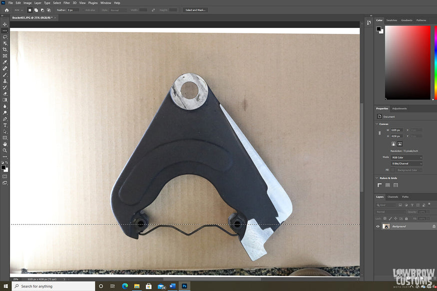
Step 1, use a horizontal line to square the image.
Next, I cropped the photo in half, right down the centerline.
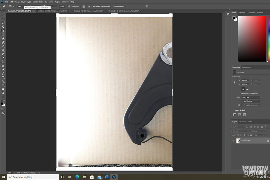
Step 2, crop the image down the vertical center line.
Now I had the half of the bracket I wanted to copy. I created a new blank canvas and copied and pasted two copies of the cropped image onto it. Then I flipped one of the images horizontally and slid the two halves together. The result was an image of the brake bracket that I wanted to create.
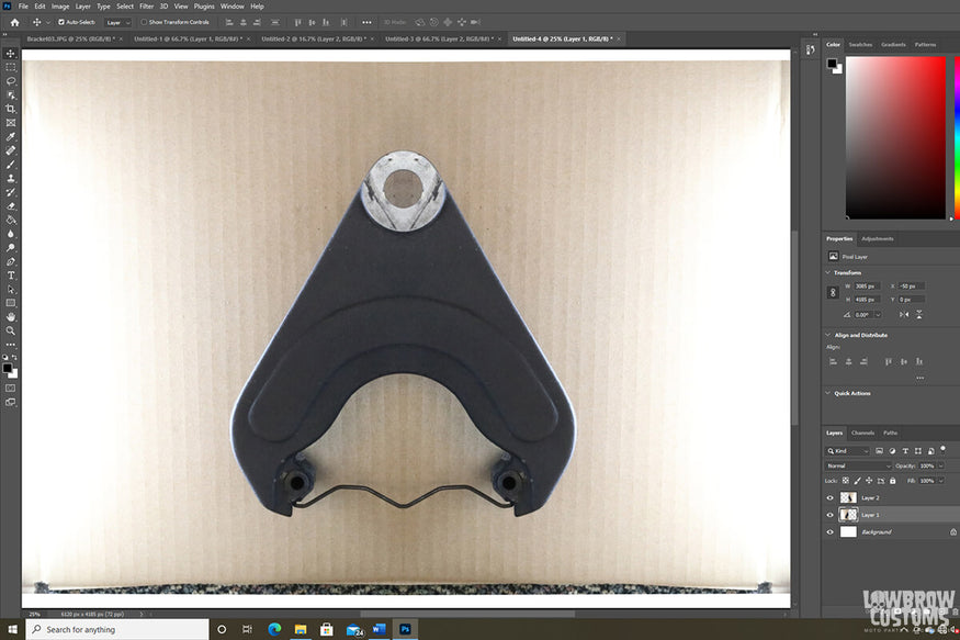
Step 3, duplicate the image and flip one copy horizontally.
Custom Brake Bracket Design
This bracket looked pretty good, but it was not exactly what I wanted. I still needed to add a tab for the brake stay. Since I had extra material on the side of the bracket where the brake stay needed to be, I decided to just keep some of the material. The question was how much? Using Adobe Illustrator, I opened both the original image and the edited image, but I changed the opacity of the original image to 30%, making it a “ghost” image allowing for the edited image to be seen through it.
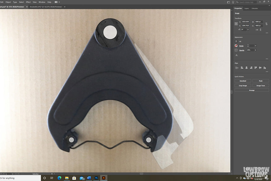
Step 4, place the original image on top of the edited image, changing the opacity to 30%.
Before going any further, I resized the image to the actual size of the bracket. I did this by measuring two points on the physical bracket and then scaled the image down until those points were the same distance apart in the image. To add the tab for the brake stay, I used the circle and rectangle tools to make a black tab with a 0.25” hole and moved it around the image until I found a location that looked like it would work.
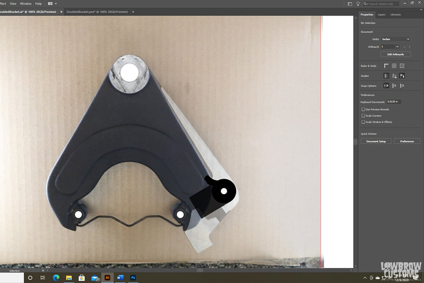
Step 5, draw the mounting bracket onto the image.
Once the basic image was complete, I rasterized everything into one layer and then traced the image. The result was an outline of the part, that could be printed and cut out by hand or in my case cut out using a laser cutter.
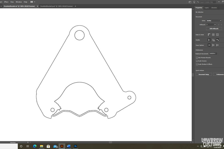
Step 6, rasterize the image and trace the outline.
Check the Fitment and Ready to Install!
I took the outline and created a template out of ¼” plywood on the laser cutter. The nice thing about using wood is it makes a nice solid template that can be mounted on the bike to check the fitment before actually cutting the part. Since I added the holes for the caliper mounting bolts, I was able to use them to line up the template and hold it steady while I traced its outline onto the brake bracket.
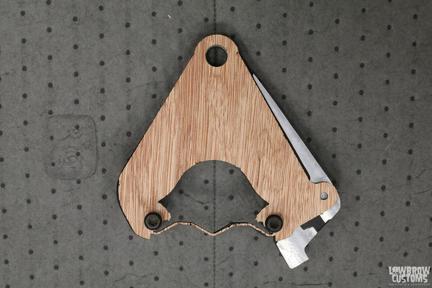
Completed template laser cut from 1/4" plywood.
Next, I used a bandsaw to cut off the larger portions of material from the bracket before using a spindle sander to clean up the edges and get everything smoothed out. Using a transfer punch, I marked the hole in the tab and drilled it out using a size Q drill. Finally, I tapped the hole with a 3/8”-24 tap.
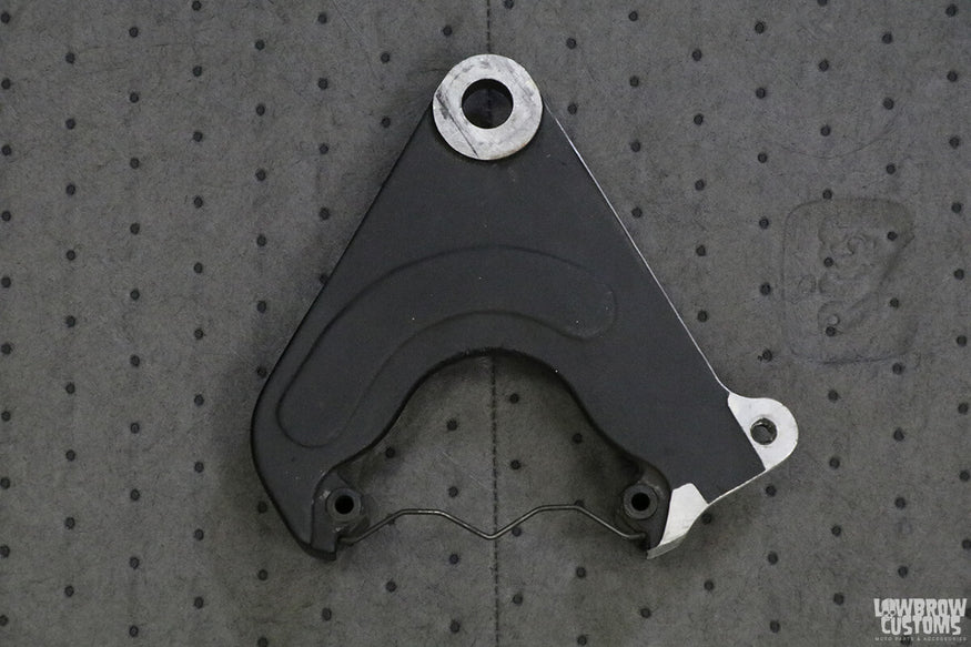
Modified stock brake bracket, ready to install.
Mount Modified Sportster Brake Caliper Bracket to the Frame
My Paugcho frame came with a tab for the brake stay already welded on, which was great, but the hole in the tab was 0.5625” which is a couple sizes too big for the hardware I was planning to use. To mount the Sportster brake bracket correctly, I made a stainless steel shouldered washer with a 0.375” hole to work with standard 3/8” hardware.
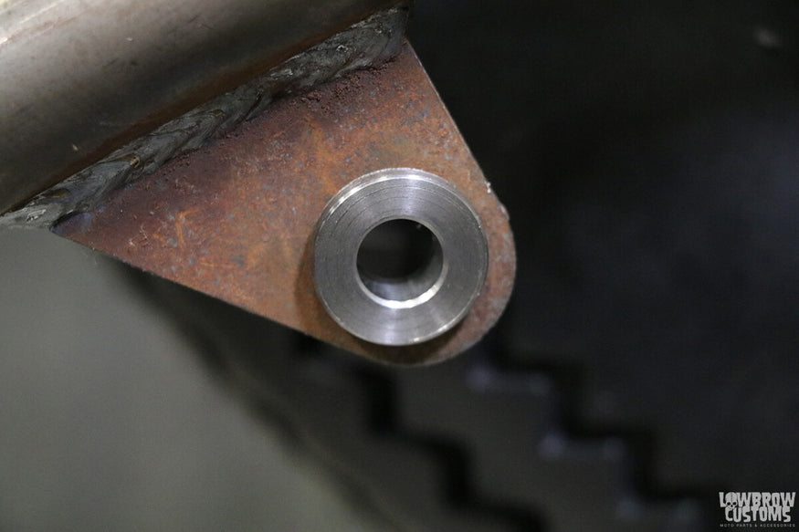
This piece does double duty as a washer and necking down the hole to 3/8".
The last piece to fabricate was the brake stay (also known as a brake caliper anchor rod) itself. Typically, these are made with two internally threaded ball joints and a piece of threaded rod. The problem is you must detach one end of the brake stay every time you want to adjust it which happens every time you adjust the rear chain.
To save a few minutes on my chain adjustments, I built my brake stay using one ball joint with right hand threads and the others with left hand threads. These are attached to a shaft with right hand threads on one end, left hand threads on the other end and hex cut in the center to accept a 9/16” wrench.
Since the threading is the opposite on each end, when you turn the shaft in one direction both ball joints spread apart and when you turn it the other direction, both ball joints come together.
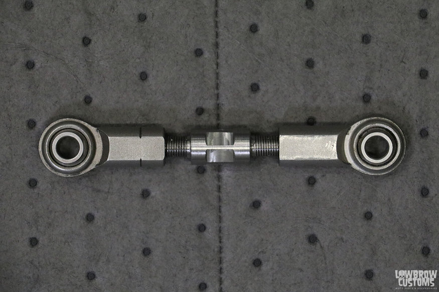
Brake stay with both left and right hand threaded ball joints.
The final brake caliper bracket installation resulted in a nice clean look with the brake caliper tucked inside the rear triangle leaving the rest of the wheel exposed. I’m definitely pleased with how it came out.
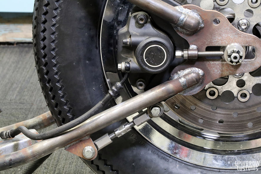
Clean and simple brake caliper set up.
Coming up next I’ll be covering that rear wheel with a Lowbrow Stingray fender and showing how to mount it to the frame.
Related Products


